Demystifying Ball Spline Specs
Place a recirculating-ball bushing on a shaft and what do you get? Frictionless movement of the shaft.
But, create grooves along the axial length of the shaft that correspond to the radius of the bushing’s ball elements and you’ve got frictionless linear movement coupled with two important characteristics – those being anti-rotation torque transfer and higher load capabilities.
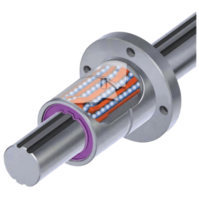
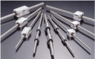
Now… that’s a ball spline. It combines a linear bushing (nut) that can now handle greater moment loads and, a shaft, which, unlike a rail, can be rotated when needed. It is perfect for high-speed motion and high-speed rotation.
There is the right ball spline for an endless number of automated operations: Robotics, inspection, spinning, loading, coating, wire winding, grinding, indexing, die setting, transferring, conveyance, molding, drafting, measuring, optical measuring, welding, riveting, printing, book-binding, packaging, filling, pressing and more.
So why isn’t identifying the right ball spline for an application straightforward and easy? Demystify the semantic differences in the literature and it will, at least, be easier. We’ll do this
by thinking of ball splines in terms of how their various configurations affect their functions and then compare their functionality to application requirements.
Six Load and Accuracy Factors
The ball spline bushing (generally referred to as a nut) has a load capacity (including moment load) that can be increased by manipulating any of seven factors – four relate to the area of ball contact, i.e., the number of grooves in the shaft, the shape of the grooves, the length of the nut and of its raceways and how close the tolerances are. Five and six are shaft rigidity and mounting systems.
Number Of Grooves In The Shaft
Compared to a slide bush’s shaft, a grooved spline shaft gives greater contact area so load capacity and life is greater than a like sized slide bush and shaft combination. The basic dynamic load ratings of a ball spline are typically 5~12 times that of a slide bush of a similar size.
The number of grooves in a spline shaft can number from two to six. However, in some instances the six groove system fills so much of the space on the shaft that there is no room next to the nut’s active ball paths for ball recirculation. Therefore, the nut has to protrude from the shaft for the balls to recirculate above and away from the shaft. Also, because the ball elements will fall out of the nut if the nut and shaft are separated, this particular type of sixgroove-shaft ball spline system must be handled with far greater care.
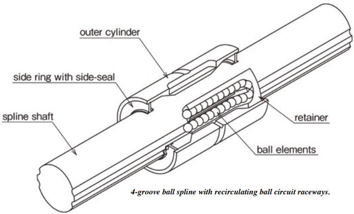
In the most popular four groove configuration, the nut can have side by side active and recirculating paths making this a much more compact system. Plus, all ball tracks are in contact
with raceways, whereas only half are in contact in any one direction on some of the six groove shaft systems.
So, if the load doesn’t require six raceways and four will do, space can be saved.
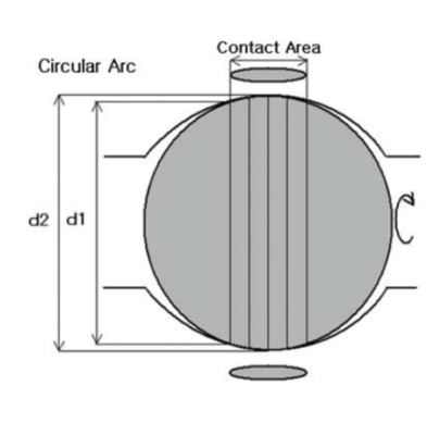
Shape Of The Grooves
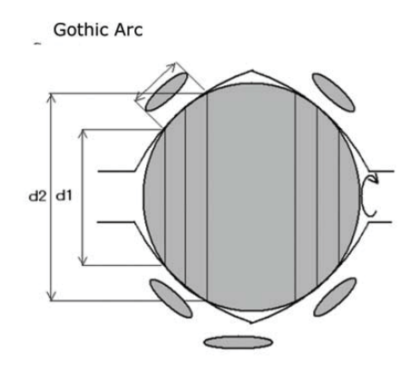
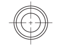
The 4-point contact design is, because of its shape, called a gothic arch. The gothic arch eliminates any clearance that could lead to deflection and is, therefore, best suited for applications requiring maximum precision. The 4 point-contact increases the load capacity and rigidity so that it can handle a greater moment load. Typically, larger spline sizes utilize the
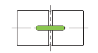
gothic arch 4-point contact grooves. Of the groove designs on the market, the standard choice is between balls that make contact with the raceway grooves at two points or at four points (see Figure 2). A slightly elliptical groove design allows the balls to make contact at two opposing points but allows a bit of clearance on the balls’ sides that are perpendicular to the contact points. A change of shaft rotation direction may cause backlash of this circular arc type nut. Because there are larger contact area differences on a gothic arc, the inner part of the balls must rotate faster than the outer, which creates slippage and results in greater friction. For this reason, circular arc grooves are used for smaller, more friction sensitive ball splines.
Length Of The Nut And Of Its Raceways
Since ball raceways are circuits, approximately half the balls in a raceway are always in the active, load-bearing portion of the raceway while the other half are in the recirculating path. The longer the nut, the more active balls supporting the load. However, some raceways are designed to more efficiently take advantage of the nuts length and pack more balls into its active portion. The more active balls in the nut’s raceways, the more moment load the nut can support. To increase moment load capacity, multiple nuts can be used in tandem.
Nut Tolerances
When raceways are precisely ground (not drawn) they better conform to the shape of the balls in the nut and grooved spline shaft. This results in opposing raceways having the same angles of contact, which eliminates backlash. The clearance between the balls and the grooved spline shaft is controlled by grinding the nut and grooved spline shaft raceways accurately and also by installing the proper ball size grade – using the nut’s bearing outer cylinder wall to adjust to the different sizes.
Each spline nut should be individually preloaded at the factory with larger ball grades that reduce the clearance between spline shaft groove and nut groove. Where less vibration and less fluctuation of torque are present, standard pre-load is sufficient to ensure smooth linear movement. For a load subjected to minor twisting, alternating moment load and vibration, a light pre-load is preferable.
Preloading decreases the available radial play to ensure rigidity, which also increases precision. This process not only increases the contact area, increasing direct loading capabilities, it also restricts any radial movement, increasing the overhung moment capabilities. This creates a sturdier structure that can handle a very demanding working environment.
Shaft Rigidity
Increasing how symmetrical the spline shaft is, can increase maximum rotational speed and load capacities as well as reduce vibration.
Spline shafts vary as to whether they are precision-ground, ground or drawn steel bar. They also vary as to the grade of the base material. Manufacturers rank shafts by characteristics such as the tolerance of ground shafts, perpendicularity to the end face, concentricity of the part-mounting section in relation to the support section, as well as the material grade.
Controlling machining of all the shaft grooves so they are linear all the way through in high accuracies is very difficult. Non-ground (drawn) spline shafts are, naturally, of lower accuracy.
Generally, manufacturers present 3 accuracy ratings comparable to High (meaning their highest precision), Medium (meaning their standard grade – usually a stock item) and Low (often a non-ground shaft). However, one manufacturer’s top grade can be another’s standard grade. Comparing accuracy grades comes down to comparing measures of the above-mentioned ranking characteristics – shaft diameter tolerance, straightness, perpendicularity and concentricity.
If a lesser degree of accuracy is acceptable because the primary concern is torque transfer, linear transfer, rotational motion or length, then drawn, non-ground spline shafts may be the best choice. Some drawn shafts can use the same nuts as ground spline, but load capacity is reduced because the nut is traveling in a non-ground raceway groove. However, they’re less expensive and can be as long as five meters, making them appropriate for material transfer and handling applications.
Mounting Systems
If the load is not mounted onto the nut securely, accuracy will be affected. There are three types of mounting systems.
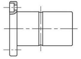
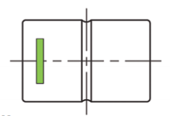
– Nut With Keyway
The standard mode of mounting a cylindrical nut is with a key. For this system, the cylindrical nut will have a keyway and separate key. A matching keyway must be bored into the housing or block that will be mounted on the cylinder nut. It is critical that the bore precisely fit the key to prevent vibration. The keyway is important because the nut has to be fixed in a rotational direction so when the grooved spline shaft is turned the nut isn’t turned within the housing. The housing has to turn with the nut. In addition to the key slot in the middle of the nut, this system also requires a snap ring, a push plate or another fixing method to prevent the nut from slipping out of the housing.
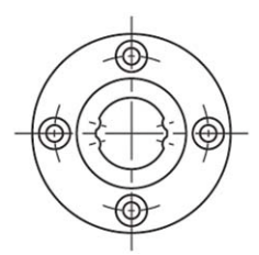
– Nut With Flange
The second mounting system is the flange nut. A flange nut is much simpler to install because it only requires a rough bore and mounting holes drilled and tapped to secure the flange to the housing. Though, to fit the nut into the housing, a hole has to be bored, this boring does not require the accuracy demanded by a keyed nut. With the flange type because it is bolted on to the housing, there is no need for a keyway.
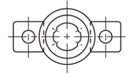
– Keyless Nut
The third mounting system is the keyless cylinder nut. It is very suitable for small size compact applications. It is similar to a flange type nut. Instead of a fixed flange on the nut, there is a squared attachment that slots into the nut to prevent rotation. The slot can be made with holes for screws so that the nut will be fixed similarly to the way that the flange is fixed to housing. But it is much more compact than the standard flange.
– Keyless Ball Spines