Whether for packaging, life sciences, office equipment or factory automation, smooth motion, fast accelerations and a high degree of accuracy are hallmark requirements for linear movement actuators. Increasingly, miniaturization has added the additional requirement of compactness. One system that can meet all of the above requirements in its conversion of motor torque to linear thrust is the single axis ball screw actuator. Ball screws convert rotary motion to linear motion, or torque to thrust, and vice versa. The ball screw actuator is a combination of a ball screw on which, to eliminate backlash, a slide block or nut’s movement is guided by recirculating steel balls that roll between the block and raceways of guide rails.
What Are The Advantages Of A System Solution?
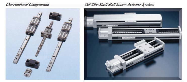
Traditionally, many equipment manufacturers designed and assembled their own, custom, ball screw actuators. In fact, many semi-conductor manufacturers and medical equipment manufacturers still do. To design custom stages, engineers have to design the ball screw size, i.e., find the right ball screw, carriage and guide rails – the three main components. They’d also have to have supports for the ball screw on both ends and motor brackets. After mounting all the components adjustments have to be made – repeatedly.
Many companies have recognized the advantages of purchasing an off-the-shelf system solution as opposed to taking components and building their own system. Typically, ball screw actuator systems come in at least 5 different stage sizes. They have several travel length options and there are other options already designed. Once the engineer identifies the optimum system, he or she just has to get the right motor.
However, to choose the right system for an application, actuator systems must be carefully analyzed. Comparisons of the design and sizing of components such as the slide block, raceway, bearing, guide rail, ballscrew, nut and housing materials are critical. They all factor into actuator performance.
How A System Solution Affects Compactness
When a ball screw actuator is designed into a product that precludes the use of off-the-shelf systems, a custom designed and assembled system may be the only answer. However, choosing to assemble ball screw actuator components such as a linear guide and a ball screw into a custom housing usually creates a larger unit overall than using a pre-designed system. For one, a pre-designed system is much more compact because the guide rail of the actuator is integrated with the structure of the actuator and the slide block has the ball screw nut incorporated into it. Generally, if you were to build an actuator from assorted components, you would have to have a housing to put a ball screw nut into. Also, there would be a separate base for linear guides. So, the entire unit would be much larger – as much as thirty percent larger.
Factors Affecting The Choice of Actuators
To choose the most effective actuator for a particular application, critical information must first be ascertained. Factors such as load capacity, operation speed, stroke length, environment, orientation, and positional accuracy have to be identified and quantified.
Assuming these factors have been ascertained, we are now going to consider the affects of component design differences on the operation of ball screw actuators in the four foot and under class.
How Component Design Affects Load Capacity
In addition to ball screw and guide rail size, load capacity depends on the size of the recirculating steel balls that roll between the block and the raceways in the guide rails, as well as the number of balls in contact with the raceways and the manner in which they make contact. One way to meet load capacity is by increasing the size of the ball screw and guide rails. Another way to increase load capacity, which does not increase the overall size of the actuator, is to increase the ball circuits. Most standard ball screw actuators have one set of recirculating balls on either side of the block (see Figure 1).
Doubling the number of ball circuits to two on either side of the block doubles the load capacity of the actuator. To wit, since we are discussing actuators of up to about four foot rail travel, an example of maximum load for a standard 1,380 mm rail length with two ball circuits is 37 kilonewton. With four ball circuits it is 74 kilonewton.
On the low end of the actuator size range, an actuator with a 100 mm length rail with two ball circuits can be expected to have a load capacity of 3.945 kilonewton whereas with four ball circuits it’s load is 7.89 kilonewton.
How Component Design Affects Precision
Actuator systems are generally offered in two or three grades – or levels of accuracy. “Commercial Grade” is the lowest; next is “High” or “Standard Grade”; “Precision Grade” is the highest. To compare systems’ levels of accuracy, one cannot assume that all manufacturers’ lowest to highest grades have comparable accuracies. It is necessary to compare their published ranges for: Positioning Repeatability; Positioning Accuracy; Running Parallelism; Backlash; and Starting Torque.
Aspects of a linear actuator that affect its precision include how true it’s guide rail and its raceways are and how smoothly in the block and raceways the balls recirculate. As the travels we’re discussing are four feet and under, the slightest deflection or clearance of the recirculating balls can significantly affect accurate movement and positioning.
In this size range, for optimum accuracy, it is critical that the guide rail be precision ground. The same can be said of the slide block and ball screw itself. Furthermore, to insure positional accuracy, the balls within the ball grooves of the raceways must not have clearance that allows them to deflect. Of the groove designs on the market, the standard choice is between balls that make contact with the raceway grooves at two points or at four points (see Figure 2). A slightly elliptical groove design allows the balls to make contact at two opposing points but allows a bit of clearance on the balls’ sides that are perpendicular to the contact points. The 4-point contact arch design is, because of its shape, called a gothic arch. The gothic arch eliminates any clearance that could lead to deflection and is, therefore, best suited for applications requiring maximum precision.
How Component Design Affects Rigidity
Ball screw actuator rigidity is affected, primarily, by the composition of the guide rail. As this is the outer structure of the system, it is the actuator’s support and its rigidity determines how consistently true the grooves of the raceways are. The thickness and strength of the lower edges of the guide rail are critical to its rigidity. A U-shaped outer rail provides better rigidity against moment loads.
A U-shaped outer rail provides better rigidity against moment loads. Guide rails positioned lower than the ball screw center also increase rail rigidity (Figure 3). When the recirculating balls’ grooves are closer to the bottom of the rail, the block can carry heavier loads. In combination 4 with the more rigid U-shaped style rail, because there’s less deformation and better accuracy, this design even allows one-end supported applications. Another advantage to guide rails positioned lower than the ball screw center is greater compactness.
Also affecting rigidity is the number of ball circuits. Four ball circuits provide greater rigidity than two ball circuits – all things being equal (ball, guide rail, block, ball screw).
How Application Speed Affects Actuator Sizing
Depending on the application, the speed at which the actuator must travel is a determinant of the length of the ball screw lead. The faster the desired travel time, the longer the lead must be. However, to achieve higher accuracy, it is best to use the shortest possible lead for the job.
There is a direct correlation of speed to length. For example, assuming the revolution of the motor were 50 rps, with a 20mm lead, the speed would be 1,000mm/s and with a 2mm lead it would be 100mm/s.
The merit of a shorter lead is that it can move a heavier load using a smaller motor. But, to achieve the same speed, if the lead is shorter, the motor must be bigger.
Dealing With Liquids And Particulate Matter In The Environment
Ball screw actuator systems are typically available with metal covers. However the standard metal covers have gaps between the cover and the guide rails. This makes them unsuitable in environments where liquids or particulate matter could enter the system – a common situation in manufacturing or fabrication applications when coolant is used. Though usually a customized option, accordian pleated bellows-type covers are available. They are designed to be impervious to fluids and particulate matter. They replace the metal cover and cover the entire guide.