For the lack of the right bearing, the kingdom of ever-faster microprocessors might have been lost. But this story has a happy ending.
Technical achievements in microprocessor manufacturing, diagnostic equipment and automation have demanded increasingly more precise motion control. Whether it’s wafer positioning for the efficient manufacture of ICs, pick and place, vision inspection, parts transfer, a microscope stage under computer control or precise vertical movements, linear bearings have had to evolve rapidly in order to carry heavier loads, take up less space and be reliably precise.
Cancer research provides a relevant example. To find one cancer cell on a slide holding a billion cells, the microscope depends on sample positioning, bringing the images into focus and moving the proper filters into place to produce an image in three colors.
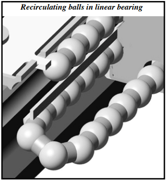
The automated movements within the instrument work in concert with one another to take multicolored images of the cellular sample that is in the chamber. Linear bearings have to meet specific requirements in order to achieve perfect positioning. These are determined by the amount of space within the product envelope, distance to be traveled, load to be carried and most critical of all, the extraordinary degree of accuracy needed. When referring to linear bearings, we generally are thinking of devices that incorporate ball bearings – meaning friction is reduced between moving parts by recirculating (usually metal) balls. Bushings, ball splines, linear guides and slides typically incorporate recirculating ball bearings.
Increasingly, as technology becomes more demanding, requiring greater and greater precision, another type of bearing has established its place in the pantheon of friction reducing devices – the crossed roller bearing. What high-tech microscopes, as well as advances in wafer manufacturing, robotics and vision inspection have in common, is their growing reliance on crossed roller bearings.
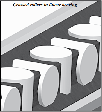
What Is A ‘Crossed Roller Linear Bearing’?
Crossed-roller slideways or bearings are the most accurate form of mechanical linear motion component. Crossed roller bearings (also known as crossed roller slides) work similarly to ball bearing slides, except that the bearings housed within the carriage are cylinder-shaped instead of ball shaped. The rollers crisscross each other at a 90° angle and move between the two parallel guides (alternately termed table and bed) that surround Crossed rollers in linear bearing the rollers. The rollers are between “V” grooved bearing ways or raceways ground out of the guides. The travel of the moving guide/table, ends when it meets an end cap, a limiting component.
As evidenced by their ubiquitous use, recirculating ball bearings have many advantages. They provide unlimited travel, and are relatively inexpensive. However, their low load capacity, short life and oscillating positioning load as the bearings recirculate, put them at a disadvantage compared to crossed roller bearings. Crossed roller slides offer a line of contact versus a ball bearing’s point contact, creating a broader contact surface that can carry a heavier load. This provides more rigidity, less deformation and thus more accuracy compared to the point contact of balls. Plus, due to the crossed rollers’ consistency of contact between the carriage and the base, erosion is much slower. The recirculation of ball bearings creates vibration when the balls leave the load carrying path to recirculate. Because most crossed roller bearings do not have recirculating components, this source
of vibration is eliminated.
Load Capacity: Resin Vs. Metal Cages
Roller-to-rail contact is key to determining load capacity. Of course, rollers provide a larger contact area than ball bearings and, since the rollers usually do not recirculate they are all carrying the load, which produces greater rigidity as well as higher load capacity than ball bearings. Balls, typically contact at a single point, though a raceway’s surfaces can be designed as curves to increase the points of contact.
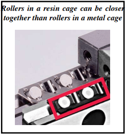
Rollers in a resin cage can be closer together than rollers in a metal cage.
There is a direct correlation between the contact area of the crossed rollers and load capacity. Load capacity can be increased as much as 250% by designs with greater roller-to-rail contact. The closer together the rollers are, the more rollers can be fitted into the same space and the more weight per inch can be carried. How the cage holds the rollers also governs the amount of roller contact area per inch. Since the amount of space between the rollers is a factor in calculating the roller surface per inch available to carry a load, the design of the cage surrounding the rollers is very important.
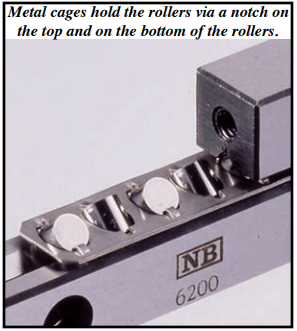
Traditional metal cages limit, somewhat, the rollers’ contact area because of the way the cage holds in the rollers. However, the more recent development of resin retainers offers more design options.
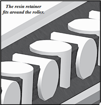
Resin retainers/cages can be shaped to allow a larger contact area with less space between rollers. They can also be thinner in critical parts. Metal and resin cages hold the rollers in completely different ways. Metal cages hold the rollers via a notch on the top and on the bottom of the rollers. However, the resin retainer fits around the roller. The resin retainer is able to harvest the whole shape to be held. The whole shape can be in contact with the load because the resin retainer exposes the necessary contact areas. It doesn’t compromose the contact area when holding the rollers.
Rollers in a resin cage can be closer together. This increases the number of allowable rollers within the cage
length. So either the cage can be shorter while maintaining the same load capacity, or while maintaining the same
cage length the load capacity will increase with the increase in the number of rollers per cage. A resin cage can afford at least a 30 to 58% increase of the contact area as compared to a metal cage.
Metal cages are less expensive and can be all stainless or steel. Therefore they can be used in high temperature
or medical applications where there is a lot of water and rust potential. Metal is also better suited in a vacuum since resin can have out-gas (such gas emission can cause problems, especially in high vacuum environments).
Travel Length
The longer the travel the longer the rail has to be. However, as opposed to recirculating-ball bushings, which have to have a shaft only as long as the travel required (since the only moving component is the bushing), with crossed roller bearings, the whole rail assembly has to be twice as long as the stroke. That’s because both rails containing crossed roller bearings move in opposite directions. So the whole assembly has to move within a space that is twice as long as the travel length. (The exceptions are in the minority of cases in which crossed roller linear guide products have recirculating crossed rollers or roller guide products that are not crisscrossed – having four circulations with opposite roller orientations. These exceptional products don’t need rails moving in opposite directions.) With a resin cage, stroke length on a given length rail can be longer because the cage can be shorter for a given load.
Travel Limits
The length of travel is, first of all, limited by the space available for the rails within an application. Since the rails move in opposition to each other, the space required is twice the distance that the load will be carried. An endstop limits travel length. They can only extend (in opposite directions) until they hit the endstop. This makes crossed roller bearings unsuitable for applications that require long strokes. However, because there is little or no difference between static and dynamic frictional resistances – even under low-load conditions – crossed roller bearings are well suited for minute motion.
Wear
For motion control applications with extremely fast acceleration and deceleration (at dimensions ranging from
30-600mm lengths, 2-12 mm rollers) endurance can be 150 million cycles.
In crossed roller bearings without anti-cage creep mechanisms, cage creep may necessitate the replacement of
guides and readjustment of the machine or installation. This affect often occurs as a result of high acceleration and uneven preloading or load distribution, as well as orientation (inclined or vertical orientation can easily cause creep).
Smoothness
A benefit of not recirculating is less frictional resistance fluctuation making them extremely quiet and smooth.
Crossed roller bearings are almost as quiet as cage-limited non-recirculating linear bearings using balls.
Accuracy and Deflection
Crossed rollers provide a larger contact area than ball bearings. That reduces elastic deformation. Because of this greater stiffness, crossed rollers provide consistently precise movement. The crossed roller is less forgiving of mounting surface inaccuracies because of the linear bearing’s rigidity and the way that they are designed. They’re much less forgiving of an inaccurate mounting surface than recirculating ball bearings are. For
recirculating ball bearings precision, 5 – 10 microns of deflection is accommodated. Because crossed roller bearings are so precise, they must have a very accurate mounting surface to fully ensure their accuracy. Often the bearings can be specified with mounting tables hone to exacting standards. This makes sense since, for ultra-precision, 2 microns is the maximum allowable deflection from the mounting surface.
Fit/Interchangeability
The cage in any bearing prevents ball to ball or roller to roller contact, which can cause more friction and wear.
Whether the cage holding crossed roller bearings are metal, resin or some other material, it alters, somewhat, a
crossed roller bearing’s dimensions. This affects how they fit into a product design. Stoppers can also affect their size and therefore their fit.
Resin, as opposed to metal cages, allows the crossed rollers to be much closer together allowing the total number of rollers to be greater in the same space. Also, because of the additional contact area allowed by a resin cage, load capacity will be higher, as well. In any case, it is prudent to contact the manufacturer and provide them with the required stroke length in order to accurately determine rail and cage lengths before ordering. In addition to stoppers and the cage material and design, another factor that affects interchangeability is the design of the anti-creep mechanism. These mechanisms will be discussed under “Anti-Creep Mechanisms”. External anti-creep mechanisms often obviate interchangeability. Internal mechanisms are much more accommodating.
Cage Creep
In non-recirculating linear components, the retainer floats between the rails and can drift (or creep) from center
position. As the roller cage creeps away from center, it will begin to restrict the slide’s travel. It will creep over time if a full stroke is not being used; especially when mounted vertically. If, after the retainer drifts, the full stroke is once again used, the retainer will hit the endstop of the rail and be forced to skid in order to center itself again. This action requires a strong motor and can damage the retainer, the rollers and the slideway. With higher preload, it is even more difficult and damaging to skid the cage back in place. Cage creep is damaging because every time it creeps, rolling elements are not rolling, instead they are slipping and causing metal to metal rubbing, which will wear out elements very quickly.
Anti-Cage Creep Mechanisms
The term “anti-creep” is used to describe the method of eliminating any slippage of the retainer holding the
crossed rollers between the two V-grooved rails of the slideway. Without creepage, downtime is reduced lowering
the cost of maintenance.
An anti-creep device eliminates this ‘creeping’ of the retainer, so the slideway can be used in any mounting
direction and with lower momentum motors such as linear motors. Several complex anti-creep devices have been
developed. To prevent cage creep/slippage, manufacturers have used a few different approaches, such as a rack and
pinion mechanism; an external attachment made of plastic gears outside of the rail; and a metal gear inside of the
rail. Some of these devices are quite expensive.
There is one mechanism that does not use a gear. It is an anti-cage creep mechanism that uses a roller with round balls studded around its surface. It has the smoothest tracking motion and therefore is quieter than an externally attached toothed-gear type anti-creep device. In this (Studroller™ – Patent Pending) mechanism, creepage is prevented because the raceway has depressions that track the studs or nodules, preventing slippage – in any position.
By placing studs in the center roller and machining a path along the rail, this retainer will never slip. It is suitable for high acceleration, vertical mounting, and uneven load distribution.
Costs vary for crossed roller bearings with anti-creep mechanisms – depending on the complexity of their design and whether the application has to be custom designed to accommodate them. Since the Studroller ™, being the simplest non-slip design, uses a ball bearing, as opposed to a gear or exterior control, it’s cost is almost the same as a standard slideway – almost half the cost of other anti-creep devices plus, there are no redesign costs to replace a standard slideway.
Applications
Crossed roller bearings are very popular in high precision applications that require very smooth motions and that
don’t require lengthy stroke travels, such as microscope stages, medical applications, semi-conductor processing,
optics lab stages, manufacturing, photonics, telecommunications, clean rooms, vacuum environments, material
handling and automation machinery.

